Septic System Diagram Library
Greenville Septic Repairs Research is the research and reference section of GreenvilleSepticRepair.com, an independent service-request platform that does not perform septic work.
Last source-verified: · Library version 1.0
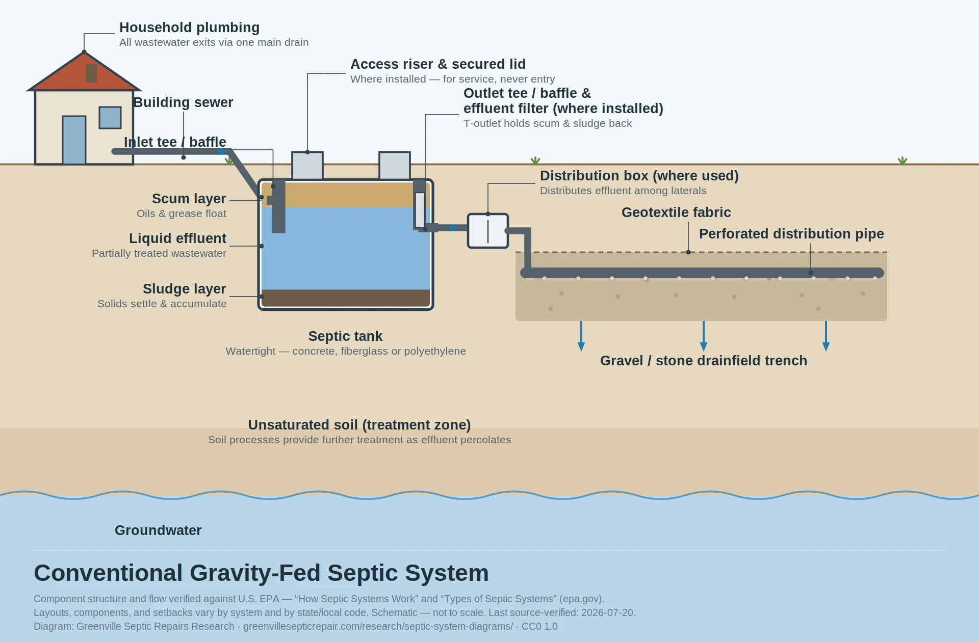
A conventional septic system diagram shows how wastewater leaves a building, passes through a watertight septic tank— where solids settle into sludge and oils and grease float as scum — and moves to a drain field. In a conventional soil-based system, unsaturated soil provides further treatment and dispersal as the effluent percolates through the soil; alternative systems can use different treatment and discharge paths. That basic idea is widely shared. The partsare not: the U.S. Environmental Protection Agency describes ten common types of septic systems, and features people treat as standard — a distribution box, an effluent filter, a two-compartment tank — appear in some designs and are absent in others.
So the most useful thing a diagram can tell you is which pieces are core to the system it shows and which depend on your design, your site, and your county. This library is built to answer exactly that, and every illustration here was drawn from a blank canvas and checked, label by label, against primary technical material from the U.S. EPA and the South Carolina Department of Environmental Services (SCDES). The diagrams are released under a CC0 public-domain dedication — free to reuse, adapt, and republish, no permission or attribution required.
Five septic-system components that are not universal
Even the “standard” diagram above shows parts that many real systems don’t have. This is the correction the whole library is built around.
| Component | Status |
|---|---|
| Distribution box | Common, not universal |
| Effluent filter | Design- or jurisdiction-dependent |
| Multiple tank compartments | Common, but configuration varies |
| Riser to grade | Common, not universal |
| Exact setbacks, depths, slopes, and capacities | Site- and jurisdiction-specific |
Source: Greenville Septic Repairs Research classification, based on cited EPA technology pages and SCDES materials; source-verified . The full component matrix is below.
Jump to a section
More diagrams — the septic tank interior, drain-field cross-section, and the alternative-system types below — are being drawn in the same style and added as each one is source-verified.
Conventional Septic System Diagram: How It Works
A conventional septic system carries household wastewater through a building sewer into a watertight septic tank, where heavier solids settle into sludge and oils and grease rise as scum. The clarified liquid in between — the effluent — flows out to a drain field, where it filters down through unsaturated soil that provides further treatment before the water reaches groundwater. According to the EPA (page last updated June 10, 2026), this tank-plus-drain-field arrangement is the typical setup for a single-family home.
The flow, step by step:
- Wastewater leaves the house through a single building sewer.
- It enters the septic tank — a buried, watertight container, usually concrete, fiberglass, or polyethylene.
- Heavier solids sink and accumulate as a sludge layer.
- Fats, oils, and grease rise and form a scum layer.
- The clarified effluent in the middle exits through the outlet. The EPA notes that internal compartments and a T-shaped outlet keep scum and sludge from escaping toward the drain field.
- The drain field releases that effluent into unsaturated soil, which provides the final treatment and dispersal.
What varies here. On a real installation, the distribution box may be present or replaced by another distribution method; the effluent filter is fitted on some tanks and not others; the tank may have one or multiple compartments; the drain-field medium may be gravel, chambers, or another approved product; and every dimension, slope, and setback is set by local code. The component status matrix marks which is which.
What Is Inside a Septic Tank?
Inside a septic tank, gravity does the first stage of treatment: heavier solids settle into a sludge layer at the bottom, oils and lighter solids float up into a scum layer at the top, and the liquid effluent sits in the clear zone between them and exits through the outlet toward the drain field. A tank normally stays full to its operating liquid level; what changes over time is the sludge and scum, which accumulate between pump-outs — so a cross-section shows the order of the layers, not fixed measurements.
| Layer | What it is | Where it goes |
|---|---|---|
| Scum | Fats, oils, grease, and lighter solids that float | Retained in the tank |
| Effluent | The clarified liquid between scum and sludge | Exits to the drain field |
| Sludge | Heavier solids that settle | Retained until pumped out |
Source: U.S. EPA, How Septic Systems Work; source-verified .
The inlet and outlet tees(sometimes called baffles) force incoming and outgoing flow below the scum layer, so floating material can’t shortcut to the outlet. The T-shaped outlet is what the EPA specifically credits with holding scum and sludge back. And one point worth stating plainly: not every tank has two compartments.The EPA’s technical material describes single- and multiple-compartment tanks, so a two-compartment drawing is one common configuration, not a universal one. (The septic-tank interior cross-section diagram is in production and will appear here.)
What Are the Main Septic Tank Parts and Access Points?
A septic-tank parts diagram identifies the inlet and outlet ends, the tee or baffle locations, the access openings and lids, any risers brought up to grade, and — where fitted — an effluent filter. Which of those a given tank actually has is design- and jurisdiction-dependent, so a useful parts diagram labels the optional pieces as optional.
Access is for trained professionals, not routine homeowner use.Lids and access ports provide access for inspection and service; risers, where installed, can bring that access closer to grade and reduce digging. Not every lid sits at grade, and not every opening has a riser. This is a safety point, not a stylistic one — see Safety below. Any South Carolina construction details, such as tank-access or tee requirements under SCDES Regulation 61-56, belong in a clearly labeled state note, never baked into a national drawing as if they applied everywhere. (The septic-tank parts and access diagram is in production.)
How Are a Distribution Box and Drain Field Arranged?
In one common conventional layout, effluent leaves the tank, enters a distribution box, and the box distributes the flow among several drain-field laterals. But a distribution box is not universal. Other approved systems distribute effluent differently — through pressure manifolds, drip tubing, or serial trenches — so a plan-view drawing showing a D-box is one arrangement among several.
On the point of universality, University of Georgia Extension is explicit: it describes a distribution box as something that may sit between the tank and the field lines (UGA Extension, B1421). We label the box “where used” for that reason — treating a common component as a universal requirement is one error this library is designed to prevent. (The distribution-box and drain-field layout diagram is in production.)
How Does a Drain Field Treat and Disperse Effluent?
A drain field distributes septic-tank effluent into a subsurface soil-treatment area, where it filters down through unsaturated soil and is treated by physical and biological processes before reaching groundwater. In the long-standing gravel design, the EPA describes effluent piped to a shallow trench of stone or gravel, with a geotextile fabric laid over the stone so soil doesn’t clog it, and microbes finishing the treatment in the soil below.
Two things this kind of diagram should never imply. First, gravel isn’t the only medium — the EPA also describes chambers and other units that do the same job without stone. Second, there is no universal trench depth, separation distance, or soil profile; those are determined by a site evaluation and local code. The one thing worth emphasizing is that the soil is doing active treatment, not simply letting water disappear. (The drain-field soil cross-section diagram is in production.)
Which Septic System Diagram Matches the System You Are Researching?
Match a system by its defining treatment or distribution component, not simply by the shape or color of its tank. The comparison below distinguishes gravity flow, pump dosing, chambers, shallow drip tubing, aeration, constructed mound sand, and recirculating filtration across the common system types — and cites the primary source for each. It’s the missing answer for a reader who knows a component name but not which diagram they need. (EPA notes that less than one-third of U.S. land area has soil suited to a conventional soil absorption system, which is why so many alternatives exist.)
| System type | Defining feature | Flow | Added mechanical / electrical parts | Final dispersal | Primary source |
|---|---|---|---|---|---|
| Conventional (gravity) | Septic tank feeding a gravel/stone or chamber trench | Gravity | None | Effluent percolates through unsaturated soil | EPA, How Septic Systems Work / Types of Septic Systems |
| Chamber | Gravelless connected open-bottom chambers replace the gravel trench | Gravity (or dosed) | None, if gravity-fed | Soil beneath and around the chambers | EPA, Types of Septic Systems |
| Pressure distribution / low-pressure pipe (LPP) | Small-diameter perforated laterals dosed under pressure | Pump-dosed | Pump, dosing chamber, level controls, high-water alarm, supply manifold | Shallow pressurized soil absorption field | EPA, Low-Pressure Pipe Systems fact sheet (EPA 832-F-99-076) |
| Drip distribution | Shallow drip tubing set in the upper 6–12 inches of soil | Pump-dosed (timed) | Dose tank, timed pump, electrical controls | Drip laterals in shallow soil | EPA, Types of Septic Systems |
| Aerobic treatment unit (ATU) | Oxygen injected into the treatment tank | Powered aeration | Air pump/aerator; optional pretreatment and disinfection | Soil dispersal, or further treatment | EPA, Types of Septic Systems |
| Mound | Constructed sand mound built above natural grade | Pump-dosed | Pump chamber | Native soil below the constructed mound | EPA, Types of Septic Systems |
| Recirculating sand filter (RSF) | Part of the filtered effluent is recirculated through a sand filter | Pump-dosed (recirculating) | Recirculation tank, dosing pump, controls | Drain field, after filtration | EPA, Recirculating Sand Filters fact sheet (EPA 832-F-99-079) |
Source: Greenville Septic Repairs Research, compiled from the U.S. EPA sources named in each row; source-verified . Free to reuse under CC0 1.0. Each system’s dedicated diagram is being produced and will be linked from this table as it publishes.
A short read on each:
- Chamber— A series of connected open-bottom chambers replaces the gravel trench; pipes carry effluent from the tank into the chambers, and the wastewater contacts the soil beneath them. The EPA notes gravelless designs like this have been used for over 30 years and are now conventional in many states.
- Pressure distribution / low-pressure pipe— A pump and dosing chamber push effluent through small-diameter perforated laterals under pressure rather than by gravity. The EPA’s LPP fact sheet lists the main parts as a septic tank or aerobic unit, a pumping chamber (pump, level controls, high-water alarm, and supply manifold), and the small-diameter perforated laterals.
- Drip distribution— Measured doses run through shallow drip tubing that the EPA describes as being placed in the upper 6 to 12 inches of soil. Actual permitted depth and configuration remain design- and jurisdiction-specific; the system also needs a large dose tank and electrical components.
- Aerobic treatment unit (ATU)— Injects oxygen into the treatment tank. The added oxygen increases natural bacterial activity and provides additional treatment for nutrients in the effluent; some systems add a pretreatment or final treatment stage with disinfection.
- Mound— Pumps effluent into a constructed sand mound above natural grade, where it filters down through the engineered sand and disperses into native soil. The EPA lists mounds as an option where shallow soil, high groundwater, or shallow bedrock rules out a conventional field.
- Recirculating sand filter— Pretreated effluent flows to a recirculation tank, where raw septic-tank effluent and filtered sand-filter effluent are mixed and pumped back through the sand filter; part of that flow is returned for another pass and the rest moves forward to dispersal. The returning loop is what makes it recirculating (EPA 832-F-99-079).
Which Septic-System Components Are Core, Common, Optional, or System-Specific?
Not every part in a familiar septic drawing appears in every installation. This is the reference we built the library around: it separates the process elements that are core to a given system from features that are merely common, optional, or specific to one design or jurisdiction. We assembled it by reading each component against EPA and SCDES primary material and classifying it — the kind of table you would otherwise have to build from several agency sources.
| Component or concept | Status | Applies to | Source |
|---|---|---|---|
| Building sewer | Core | Individual onsite-system diagrams | E1 |
| Septic tank | Core | Conventional and tank-based systems | E1, E2 |
| Scum / effluent / sludge zones | Core process function | Septic-tank cross-sections | E1 |
| Inlet & outlet tee (baffle) | Core process function | Septic-tank diagrams | E1 |
| Multiple tank compartments | Common; configuration varies | Tank diagrams | E1 |
| Access opening & lid | Core (maintenance access) | Tank diagrams | E1, S1 |
| Riser to grade | Common, not universal | Tank diagrams | E2 |
| Effluent filter | Design/jurisdiction-dependent | Tank outlet | E1 |
| Distribution box | Common, not universal | Conventional layouts | U1 |
| Gravity flow | Core to the gravity example only | Conventional gravity diagram | E1 |
| Dosing / pump chamber | System-specific | Mound, drip, pressure, RSF | E2, E3, E4 |
| Controls & high-water alarm | System-specific | Pump-based systems | E3 |
| Aeration equipment | ATU-specific | ATU diagrams | E2 |
| Gravel / stone trench | One conventional drainfield form | Conventional diagrams | E2 |
| Chamber | Chamber-system-specific | Chamber diagrams | E2 |
| Shallow drip tubing (upper 6–12 in) | Drip-specific | Drip diagrams | E2 |
| Sand mound | Mound-specific | Mound diagrams | E2 |
| Recirculation loop | RSF-specific | RSF diagrams | E4 |
| Unsaturated soil (treatment zone) | Core to soil-based systems | Soil-based diagrams | E1 |
| Groundwater | Contextual, not a component | Reference on all diagrams | E1 |
| Exact setbacks, depths, slopes, capacities | Site/jurisdiction-specific | Excluded from general diagrams | S3 |
Source: Greenville Septic Repairs Research; source-verified . Classifications are an editorial synthesis of the primary sources keyed below. Free to reuse under CC0 1.0.
“Drain Field” vs. “Leach Field” vs. “Soil Absorption Field”
These three terms usually name the same thing: the subsurface area where septic-tank effluent is distributed for final treatment and dispersal in the soil. The naming varies by source and region, which trips up readers matching a permit or inspection report to a diagram.
| Term | Used by | Refers to |
|---|---|---|
| Drainfield / drain field | U.S. EPA | The soil treatment and dispersal area |
| Leach field | U.S. EPA and common usage | The same soil treatment and dispersal area |
| Soil absorption field | SCDES and other agency materials | The same soil treatment and dispersal area |
Source: Greenville Septic Repairs Research, from EPA and SCDES terminology; source-verified .
The EPA itself uses both “drainfield” and “leach field,” so if your permit says “soil absorption field” and a diagram says “drain field,” you’re almost certainly looking at the same component.
What These Diagrams Show — and What They Don’t
These diagrams explain how wastewater flows, how the treatment stages work, and how the components relate. They do not establish a specific property’s system location, dimensions, capacity, setbacks, condition, permit status, or suitability for excavation, repair, or installation. They’re the right tool for understanding a type of system, and the wrong tool for making decisions about a particular one.
Educational schematic vs. as-built record.For your actual installed layout, the authoritative document is your property’s permit and its final-inspection record — for a South Carolina property, that completed record is intended to reflect the system as actually installed, which a generic internet illustration cannot. That record, not a diagram, is where to start. (If you need to track one down, see our companion research on South Carolina septic permit records.)
These are also not installation, excavation, or locating guides. They carry no dimensions, equipment instructions, or dig procedures, by design.
Safety: Never Enter a Septic Tank
No diagram in this library depicts a person opening, entering, or reaching into a tank, and none should be adapted to. This is the one place where a “just educational” drawing can cause real harm if it’s drawn carelessly, which is why we treat tank-entry imagery as off-limits.
How We Produce and Source-Check These Diagrams
We built this library to give writers, educators, and homeowners one consistent, verifiable visual reference instead of a scattered mix of agency PDFs, watermarked contractor graphics, and paywalled stock. Here’s exactly how we work, so you can judge it.
For each diagram, we first map its process steps and every label to primary material from the U.S. Environmental Protection Agency and the South Carolina Department of Environmental Services — we read the sources rather than summarize a summary. We then classify every consequential component as core to the represented process, common but not universal, optional, system-specific, or jurisdiction-dependent, and record it in a label ledger before the diagram is drawn. Each illustration is drawn as original artwork from a blank canvas; we do not trace, recolor, reproduce, or lightly modify EPA, government, stock, manufacturer, or competitor illustrations. Before a diagram publishes, we check it against its label ledger, export it into each listed format, test it for legibility at mobile and print sizes, and assign it a version and a source-verification date.
A word on what we do and don’t claim. We say these diagrams are source-verified against EPA and SCDES material— because that’s what we did. We do not claim they were “technically reviewed,” “engineer-approved,” or “reviewed by a licensed septic professional,” because no such review has taken place. If a qualified reviewer is ever engaged, we’ll name them, state what they reviewed, and date it. The diagrams are conceptual and not to scale, and they don’t replace a permit, an as-built drawing, a site evaluation, a system design, an inspection, or professional advice.
Label source ledger — conventional system diagram (D01)
Every label in the diagram above traces to a primary source. This is the ledger we verified it against.
| Label / claim | Classification | Primary source | Verified |
|---|---|---|---|
| Wastewater exits the house via one building sewer to the tank | Core process | EPA, How Septic Systems Work | 2026-07-20 |
| Watertight tank; concrete, fiberglass, or polyethylene | Core process | EPA, How Septic Systems Work | 2026-07-20 |
| Solids settle as sludge; grease floats as scum; effluent between | Core process | EPA, How Septic Systems Work | 2026-07-20 |
| Inlet & outlet tees / T-outlet hold scum and sludge back | Core process | EPA, How Septic Systems Work | 2026-07-20 |
| Access riser & lid — “where installed” | Common, not universal | EPA, How Septic Systems Work; SCDES | 2026-07-20 |
| Effluent filter — “where installed” | Design/jurisdiction-dependent | EPA, How Septic Systems Work | 2026-07-20 |
| Distribution box — “where used”; distributes among laterals | Common, not universal | UGA Extension B1421 | 2026-07-20 |
| Gravel/stone trench with geotextile over clean stone | One conventional form | EPA, Types of Septic Systems | 2026-07-20 |
| Effluent percolates through unsaturated soil to groundwater | Core process | EPA, How Septic Systems Work | 2026-07-20 |
Publisher: Greenville Septic Repairs · Research section: Greenville Septic Repairs Research · Last source-verified: · Library version: 1.0
Septic System Diagram Downloads and File Formats
The conventional-system diagram (D01) PNG and WebP are available to download now. Downloads are free and require no email, account, or form. SVG, PDF, grayscale, and unlabeled formats are in production and will be added in the same table. Additional diagrams are added in the same formats as each is source-verified.
| File | Format | Best for | Status |
|---|---|---|---|
conventional-septic-system-diagram.svg | SVG (color, labeled) | Web use and clean scaling to any size; editable vectors | In production |
| conventional-septic-system-diagram.png | PNG (color, labeled) | Dependable rendering in documents and slides | Available now |
| conventional-septic-system-diagram.webp | WebP (color, labeled) | Faster-loading web images | Available now |
conventional-septic-system-diagram.pdf | Print-ready PDF | Handouts and print | In production |
conventional-septic-system-diagram-grayscale.svg | SVG (grayscale) | Low-cost printing and photocopy-friendly reproduction | In production |
conventional-septic-system-diagram-unlabeled.svg | SVG (unlabeled) | Worksheets, quizzes, and custom labeling | In production |
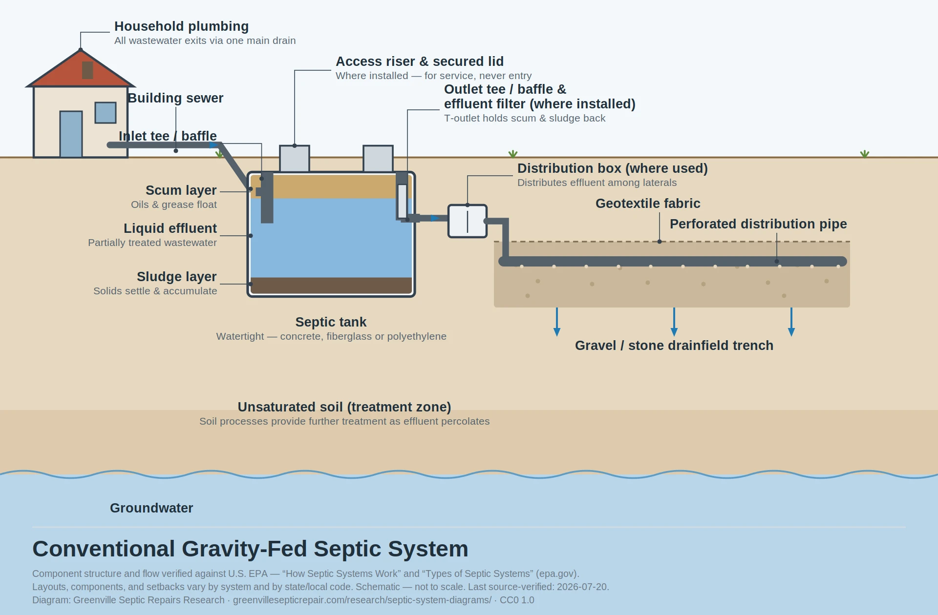
All files: Greenville Septic Repairs Research · CC0 1.0 · source-verified . A machine-readable manifest and a full ZIP package will be published once more diagrams are complete.
Reuse Rights
The original diagrams and the original data tables in this library (the component status matrix, the system comparison table, the terminology reconciliation, and the source ledger) are released under a CC0 1.0 Universal public-domain dedication. You may copy, modify, and redistribute them — including commercially — without asking permission, and attribution is not required. CC0 applies only to original Greenville Septic Repairs work; it does not apply to third-party source material, agency trademarks, or linked government publications, which remain the property of their respective owners. No endorsement by Greenville Septic Repairs, the EPA, SCDES, or any other source is implied.
If your publication keeps image credits or a bibliography, a source record is provided below for your convenience — but using it is entirely your editorial decision, not a condition of reuse.
Citation Information
For bibliographies and image-credit systems, here is the reference for this page and a per-diagram source record. This is neutral attribution information of the kind research publications provide; it is not a request to link.
How to cite this page
Per-diagram source record (example)
Primary Sources
- U.S. EPA — How Septic Systems Work (page last updated June 10, 2026): conventional flow, tank separation, drain-field treatment in unsaturated soil.
- U.S. EPA — Types of Septic Systems (page last updated May 4, 2026): the ten common conventional and alternative system types and their descriptions.
- U.S. EPA — Decentralized Systems Technology Fact Sheet: Low-Pressure Pipe Systems (EPA 832-F-99-076): pressure-distribution components and dosing.
- U.S. EPA — Decentralized Systems Technology Fact Sheet: Recirculating Sand Filters (EPA 832-F-99-079): the recirculation loop and forward flow.
- South Carolina Department of Environmental Services (SCDES) — septic-tank safety guidance, permit and final-inspection records, and Regulation 61-56: South Carolina terminology, records, and tank-entry safety.
- University of Georgia Extension — A Beginner’s Guide to Septic Systems, Bulletin B1421: homeowner-level explanation, including that a distribution box may be present.
Version History
| Version | Date | Change | Basis |
|---|---|---|---|
| 1.0 | Initial library: conventional-system diagram published; component-status matrix, system comparison table, terminology reconciliation, label ledger, and methodology established | EPA and SCDES primary sources, source-verified |
We distinguish technical changes (a corrected label, a redrawn component, an updated source) from cosmetic ones, and we update the “Last source-verified” date only when the underlying content is actually rechecked.
Frequently Asked Questions
Is a generic septic system diagram the same as my property’s layout?[expand]
No. A diagram like these explains a system type or process. For your actual layout, use your property’s completed permit, as-built record, or other official installation documentation — for a South Carolina property, that record is intended to reflect the system as installed.
What’s the difference between a drain field and a leach field?[expand]
They’re two names for the same thing: the subsurface area where effluent is distributed for further treatment and dispersal in the soil. The EPA uses both “drainfield” and “leach field,” and other materials call it a “soil absorption field.”
Does every septic system have a distribution box?[expand]
No. A distribution box appears in many conventional layouts, but other approved systems distribute effluent differently. UGA Extension describes it as a component that may be present between the tank and the field lines.
Does every septic tank have two compartments?[expand]
No. Tank configuration varies by age, product, design, and jurisdiction; the EPA describes both single- and multiple-compartment tanks. A two-compartment drawing is one common configuration, not a universal one.
Can I use these diagrams to locate or excavate my tank?[expand]
No. They are not property maps or locating instructions, and they carry no dimensions. To find your actual system, start with your permit or installation record.
Which file should I use for a presentation, and which for print?[expand]
For presentations, use the SVG (after confirming your software supports it) or the PNG for dependable rendering. For print, use the vector PDF or SVG so the diagram stays sharp at any size.
Can I reuse these diagrams on my own website or in a course?[expand]
Yes. The original artwork is released under CC0 1.0, so you can copy, modify, and redistribute it — including commercially — without asking permission or providing attribution.
Need septic service in Greenville, SC?
This site connects homeowners with independent septic providers for pumping, drain-field repair, inspections, and installation in the Greenville area. Request service →